Part 1 - the basics
Many of my designs are based around CMOS chips and a few people has asked me if I know any good resource for stompbox designs based on CMOS. So I thought it might be fun to share alittle of my knowledge of the CMOS basics and hopefully you will learn something and will be able to experiment with your own CMOS based circuits. :)
We will use the breadboard later, but first, lets start with the basics (the boring stuff...)
CMOS chips are based on MOSFET transistors, unlike the earlier TTL logic chips that are based on BJT transistors. I won't go into detail on how they work on the insides. For that I really recommend reading the book: The CMOS Cookbook. It's been a huge help and inspiration for me.
Logic
The first thing one must understand is that CMOS chips are (mostly) used for digital logic - The output will be either high or low, depending on the voltage at the input(s). Most logic gates have an input threshold at about half the supply voltage.
These input/output states are often also called "high or low", "true or false", "on or off", "1 or 0". When the output is low, it sinks current. When the output is high it sources current.
High = the output goes to the positive supply rail
Low = the output goes to ground
Keep in mind that there's a limit on how much current the outputs can source and sink which can vary between different CMOS chips. Check the datasheet for the chip you are using, especially if you are driving LED's directly, then you need to use a current limiting resistor that is big enough to not draw more current than the the output(s) can handle.

The Arcadiator uses 3 CMOS chips

Don Lancasters CMOS Cookbook
Gates
A single CMOS input/output is called a "Logic Gate". Sometimes each gate can have several inputs. A chip usually consists of several identical gates that can be used independently. In the datasheets we will find something called a "Truth Table". It tells us how the gates operates based on their logic type. Lets take a look at a few different chips and their logic.
This means that no matter which kind of waveshape we put into a typical CMOS logic chip, the output will always be a square wave (with the exception of the CD4049/4069 that can be configured as a linear amplifier). There is no in-between, no dynamic range, it's either high or low.
- Buffer (CD4050)
This chip is rarely used. But I wanted to use it as an example. As you can see by the Truth Table, if the input is high the output is high, and if the input is low the output is low. So this chip is simply a buffer (mostly used for interfacing to TLL logic).

- Inverter (CD4069/CD4049)
This chips, also sometimes called a NOT gate (or hex inverter because the chip has 6 gates), inverts the input. If the input if low, the output is high and vice versa. The output is 180 degress out of phase with the input. Notice the small circle (knot) at the output on the schematic symbol. This means that the gate is inverting.
This is probably one of my favourite CMOS chips since they also can be configured as linear amplifiers aswell. More about that later.

- AND GATE (CD4081)
This chip has four AND gates. Each gate has two inputs. With either or both inputs low, the output will be low; with both inputs high, the output will be high.
Both input A and input B needs to be high for the output to be high, hence the name "AND gate".

- NAND gate (CD4011)
This is basically the same as a AND gate, except that it inverts the output. It can be useful when doing gated oscillators. I used a NAND schmitt trigger chip (the CD4093) for that application in my Flawed Logic Fuzz.
NAND stands for "NOT AND". Remember that a NOT gate is an inverter.

- OR gate (CD4071)
This chip has four OR gates. Each gate has two inputs. With either or both inputs high, the output will be high; With both inputs low, the output will be low.
Input A or Input B needs to be high for the output to be high, hence the name "OR gate".

- NOR gate (CD4071)
You can probably guess by now that the NOR gate (NOT OR) is an inverting OR gate, so I will not add the NOR gate schematic symbol and truth table.
NAND and NOR gates are sometimes called the universal gates, since they can both be used to form all the other basic logic gates.
- XOR GATE (CD4070)
This chip has four Exclusive OR gates. It also has two inputs per gate. It's a very versatile chip, because one of the inputs decides if the gate is inverting or non-inverting by tieing the input to either +V (non-inverting) or ground (inverting). This chip can also be used as a comparator as identical inputs gives a low output and different inputs gives a high output. So basically, if two different signals is put into the two inputs the output is the sum of the differences of those two (hence the name "exclusive or gate"). This is partially how my ring mod The Corruptor works. - XNOR gate (CD4077) - Same as the xor but inverted.

- SCHMITT TRIGGER (CD40106)
Here's another very versatile gate/chip. It's an inverter, but each input has has two thresholds which makes it a schmitt trigger. For example, if we use a 9 volt supply, the input signal will have to reach above 6 volts for the output to go low and it will have to drop down to belop 3 volts for the output to go high. The range in between these voltages is called hysteresis and acts as a noise immunity zone, and it also lets us configure this chip with diodes and resistors to do other logic funtions: multiple inputs NAND or NOR gates, pulse width modulation and much more.

There are some CMOS chips that have more specialized functions, like a Phase Locked Loop. Some chips can also have a third disconnected output state (floating/undefined state).
CMOS rules
When using CMOS chips, there's a few things that you need to keep in mind -
- All inputs must go somewhere. A unused gate input must be disabled by connecting it to either +9V or ground, directly or via a resistor. The input of a CMOS gate is very high impedance, so a floating input can cause the gate to change state erratically, resulting in noise and high current draw. Leave unused outputs unconnected.
- Inputs that comes off board should have a load resistor connected (1M resistor to ground).
- CMOS chips are sensitive to static. They have built in protection diodes, but sometimes it's not enough. It's a good idea to wear a anti-static wristband when working with CMOS and not pet your cat/dog.
- CMOS chips accept a wide range of supply voltages (generally from around +3v to +15v), but it's always a good idea to double check the datasheet just to sure. There are exceptions. We will only be using chips that works well with +9 volts.
Pulldown / pullup resistors
These resistors are often needed in CMOS circuits. They are useful when we want to force a high or low output state when the input is not changing, but still leave the input able to accept a input signal. They are typically a high value from 10K - 100K that is connected at the input of the gate and goes to ground (pulldown) or V+ (pullup). For example, if we have a gated oscillator on the input and we want to make sure the output always goes to ground when the oscillator is off we need a pullup resistor at the input (assuming the gate is inverting).
Part 2 - square wave fuzz
Now onto the fun stuff. :)
To be able to use a CMOS chip with a guitar signal, the signal needs to be boosted into a square wave, then turned into a pure logic level square wave using a schmitt trigger: digitalizing the signal in a crude way.
This is the reason you don't see a gain control on many of my CMOS based designs and why it often sounds totally fuzzy. A square wave sounds very distorted as the sharp edges of the square wave introduces alot of odd harmonics. This is also the reason why the output of a CMOS based guitar effect have a gated sound with a decay that dies abruptly when the input signal falls within the schmitt trigger thresholds.
Here's a short video of my oscilloscope that displays a guitar signal that is boosted to reach logic levels, then later fed through a CMOS schmitt trigger to make it a square wave so it will play along with other CMOS chips.
Lets breadboard the CMOS'ifier, a simple square wave fuzz.
We will use this circuit as the front end for the guitar signal, so we can do other things later on, such as octave down. But it also makes a pretty cool fuzz on its own.
No audio output is connected in this video, it's for the visuals only, so you can get a idea of how the waveshapes look when it's getting "CMOS'ified".
For this we will use a CD4069 chip, simply because it has a easier pinout than the CD4049 and takes less space on the breadboard. First, lets take a look at the pinout of this chip. Lets connect input/output jacks, power and ground to the breadboard and the chip like this (these connections will not be shown later).


Stage 1 - preamp
Our first stage of our circuit will be boosting the guitar signal into logic levels. This is a gainstage similar to many CMOS based distortions, such as the classic Tube Sound Fuzz by Craig Anderton. This is one of the exceptions to the digital logic and can only be done with the CD4069/CD4049. It gives a very pleasing distortion, but has the drawback of being rather noisy.
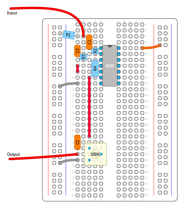
We will configure one stage of the inverter by adding negative feedback, using a resistor from the input to the output of the inverter and decoupling capacitors.
- R1: Load resistor
- R2: Sets the gain of the amplifier. Try a 1M trimmer/pot here instead for controlling the gain.
- C1 and C2: Decoupling capacitors. This is always needed at the input and output of a circuit, but it's also nessecery for the input of a linear amplifier to work properly.
- R3: voltage divider trimmer to control the output volume.
- C3: optional lowpass filter cap. Can be anything from 100pf to 47nF. How much treble it cuts depends on the value of R2 aswell. Experiment with different values!

A CMOS inverter configured as a linear amplifier doesn't need an external voltage reference for bias, so very few parts are needed to make it work. It will self bias throught the feedback resistor thanks to the operation of the internal MOSFET output pair. This works best with the unbuffered (UBE) versions of the chips.
Lets put it up on the breadboard. Notice the green wires in the first image that are used to disable all the unused inputs. This will not be shown later, but it's a good pratice to always disable any unused input. The second image shows the same circuit with a trimmer for gain control. Put several gainstages in series for a sweet sounding distortion. I usually have two gainstages in my designs when I have one extra inverter left over.


Any amplifier circuit (CMOS, transistor-based, op amp-based...) can be used to boost the signal into logic levels, but the advantage with this method is that we're only used 1/6 of one chip. So the rest of the inverters can still be used for other things, oscillators, LFO, filters ect. and this will save us some space.

Stage 2 - Schmitt Trigger
This stage completes the CMOS'ifier. It will turn the signal into a pure square wave, making it compatible with other CMOS chips and eliminating noise from the guitar pickup when not playing. This part is inserted before the output capacitor.
The relationship between R3 and R4 controls the schmitt trigger hysteresis. It's best to leave R4 at 1M and experiment with R3. Higher values will make it more gated, but low values can result in oscillation. Here we need to find the sweetspot that depends on how strong input signal we are getting. Increasing the value of C3 (1nF - 22nF) can also help against oscillation, noise and misstriggering. Very low output pickups may sound too gated, in that case use two preamp stages in series before the schmitt trigger to increase the sustain.
How does the Schmitt Trigger work exactly? R3/R4 forms a voltage divider that offset and attenuates the signal. When the output goes low, R4 is effectively connected to ground (via the second inverter output). This offsets the input signal which gets pulled closer to ground, so when the signal starts to swing in the opposite direction it has to rise a bit further to cross the half supply voltage threshold (the threshold always stays the same) and vice versa: when the output goes high, R4 is connected to your positive supply voltage via the output, so then the signal is pulled closer to V+ and needs to swing a bit lower to cross the threshold. Thus creating hysteresis. For this to work, the output needs to be non-inverting, hence the two inverter gates in series. This also helps the process as the first inverter is isolated from the feedback resistor.
You can also use a single schmitt trigger gate from a CD40106 (or CD4093) for this purpose, but they have fixed thresholds so they are less versatile and will gate the signal quite hard.
Alternative methods
Another popular method of "squaring up" a signal is to use an amplifier IC like the LM386 with max gain (pins 1 and 8 connected together) or a comparator (either a comparator IC like the LM311, or an opamp.
What is signal offset?
Any alternating current (like a guitar signal) always have a DC bias point (sometimes referred to as the DC component of the signal). It centers the signal to swing above and below a specific voltage. This DC voltage can be offset.
In a dual supply circuit, the signal usually swings positive and negative centered around ground (0 volts) and in a typical single supply circuit like a guitar pedal we create a voltage reference (Vref) that the signal swings around. Ideally at 4.5 volts in a circuit driven by a 9V battery, to get maximum usable swing.
Part 3 - octave down
Lets have a look at a few different ways to create octave down using CMOS chips.
Flip Flops
In all of the examples below we will use something called a flip flop to divide the frequency. The flip flop/latch is one of the fundamental logic building blocks. It's used to store data and is how RAM memory in our computers works. One flip flop can store 1 bit of data, which means that it can hold a high or low state until we tell it otherwise. This can be very useful, for example when we want to use a momentary switch to turn something on or off until we press it again. Flip flops can also be used as oscillators, counters and much more.
But now let's focus on frequency dividing. What it does, to put it as simple as possible: Each time the clock (our input signal) goes high, the output changes state. Since the output only changes on the positive transitions and holds that state on the negative transitions we get exactly half the frequency at the output, like this:

If you want to learn more about the logic math behind the flip flop,
I recommend this video: https://www.youtube.com/watch?v=PCT76PsDr6g
Example of a basic S-R flip flop using AND gates


Example of a flip flop latch
Pre-filtering
Making a octave down circuit with CMOS is easy since we are now working with 1's and 0's. Getting good tracking is harder, but there are a few simple measures we can take to get acceptable tracking. The first thing to keep in mind is that we can improve tracking significantly by using the neck pickup of the guitar. But we also need to add a lowpass filter after our schmitt trigger since it adds alot of high frequency content. There are many different lowpass filters we can use, varying in complexity, but for this article we'll use a simple passive RC filter.

Here is a sound example of octave down with: 1. Bridge pickup, no filter 2. Bridge pickup with RC filter 3. Neck pickup with RC filter.
Let's get the breadboard ready!
We'll start out with the circuit we made in part two, then add the new section before the output capacitor. To keep it simple, the schematics will not show the "cmos'ifier" part or the output part. Lets add the RC filter first (R6/C4). 10K and 22nF-100nF is a good starting point. Then we'll add the octave down part.
No decoupling capacitor after the schmitt trigger is needed. CMOS chips are make to interface with each other directly so decoupling caps are rarley needed, except for special cases like linear amplifiers, filters or special schmitt trigger operations. It's very forgiving this way.
Dual D-Flip Flop (CD4013)
This chips is used in the MXR Blue Box and many others.
This chip has two D-flip flops. The D prefix means that it changes output state on positive transitions only, exactly what we need. For two octaves down, we'll just put both flip flops in series so that the second flip flop will divide the output of the first flip flop.
- Input goes to Clock
- The NOT Q output (Q with a line) goes back to the data input (D) directly, or via a 10K resistor
- Set and Reset goes to ground
- Q or NOT Q goes to output. NOT Q is the inverted output
- VDD to V+ and VSS to ground

CD4013 pinout


Output controls
You can use pots/trimmers as variable resistors or voltage dividers to have control over each octave or a switch to toggle between them, a blend pot/trimmer between straight square wave and octave down ect... Experiment with the controls that you want. Here are a few examples:


Binary Ripple Counter (CD4024)
This chip is what I used in the Arcadiator. it's very common in DIY synth stuff and it's also used in for example the Bit Commander by Earthquaker Devices. It's very simple to use and require no extra external components.
The CD4024 chip is a counter that advances one count every time the clock changes from high to low. The first output is divided by two, and the next output divides the preceding output by two and so on, up to output 7 that has the input frequency divided by 128. This means that each output is one octave lower. It's basically several flip flops in series.
- Input goes to Ø
- Reset goes to ground
- Q1 is the one octave down output
- Q2 is the two octaves down output
- VDD to V+ and VSS to ground

CD4024 pinout


Part of the Arcadiator schematic
There are many CMOS IC's that can be used for frequency dividing, like the CD4013, CD4024, CD4040 and many others. Some chips that are less obvious can also be used together with other components to create frequency dividing, like the CD4069, CD4015, CD4066 and the CD4046. What kind of chip you use will not really matter sound-wise, as they all put out square waves. When I design a circuit I will often choose a chip that can do double duty and perform another task in the circuit, to minimize the overall circuit size.
NAND Gates (CD40106, CD4093)
As mentioned before, NAND gates and NOR gates are called the universal gates as they can be used to form any other combinational or sequential logic. Many CMOS IC's often include a schematic in their data sheet that show how logic gates are configured internally to perform more complex tasks such as flip flops, counters ect.
In old 70's electronics it was common to see NAND gates (TTL logic) combined to make more complex logic. Probably because there was less specialized chip available or by using the cheaper IC's to reduce cost.

NAND equivalent of a D flip flop

Mickey Mouse Logic
A schmitt trigger gate can be made into a multiple input NAND or NOR gate using 1N4148 diodes and a resistor, with as many inputs as we want. This is something I picked up from Ray Wilson that he calls "mickey mouse logic". This makes the CD40106 and the CD4093 very versatile chips. Instead of adding another dedicated NAND chip, you can use left-over gates with mickey mouse logic if needed.
Just as an experiment, I tried making the NAND equivalent of a D flipflop using nothing but Schmitt Trigger mickey mouse logic, just to see if it would work. It's a bit silly and unpractical, but it works... :)

CD40106 flip flop schematic
A good way to test these octave down circuits on the breadboard is to connect a LFO with a LED to the input and another LED at the output. That way we can easily see if it works. I tested the NAND schematic first with a freeware program called Logic Circuit just to make sure it would work, then I breadboarded it. This is the result.
For this video I used another CD40106 for the LFO. We'll cover LFO's in a later part. (Ignore the extra parts on my breadboard and the non decoupled inputs.. I cheated alittle to make it quickly...)
Post-filtering
It can be a good idea to have a RC lowpass filter on the octave output if you want it to sound less harsh. It's common to filter out anything above around 100hz to make it blend better with a clean guitarsignal. Experiment! :)
Part 4 - octave up
This part will be about octave up circuits (aka frequency doublers).
The easiest way to produce a digital octave up is by using a Pulse Generator circuit, also called a Edge Detector. It generates a pulse at every high-to-low and every low-to-high logic transition, thus doubling the frequency.
It's a simple circuit and what I used for the Arcadiator. There are several ways to do this. Let's have a look at a few examples and start with the easiest way that require the least amount of components.

The top row shows the square wave and the bottom row shows the pulses generated with the edge detector circuit

XOR (CD4070)
The CD4070 is ideal for this purpose and require very little extra components.
XOR logic: for the output to go high, both inputs needs to be at different states.
By connecting our square wave to both inputs and delaying one of the inputs slightly, there will be a brief moment when the inputs are in different states. At this moment the output will go high, thus creating a short pulse wave at the output every time the input goes high or low. The delay is made out of a simple RC filter. It will round out the square wave, so that it takes alittle longer for each transition to cross the switching threshold of the logic gate.
Lets try this circuit on the breadboard. Remember to always disable all the unused inputs.

Square to pulse schematic


Here we can play around with different values for the RC filter. It will change the width of the pulses and the character of the sound. For C5 (C1 on the schematic) try a 4.7nF - 47nF value. For R5 (R1 on the schematic) try 10K-500K. In the 1B example I've replaced R5 with a trimmer and for convenience I chose another gate. The top greyed out part is the gainstage and schmitt trigger front end from the CMOS Workshop part 2 so you will have to check the other component values there.
Notice that the pulse width can get too narrow or wide for the octave up effect to work. As a rule of thumb you don't want the pulses to be too narrow because it will sound bad, and you don't want the pulses too wide because then it won't track properly on the entire fretboard.

If you don't have any CD4070 chip at hand you can use a CD4011 chip to homecook one XOR gate our of four NAND gates.
Schmitt Trigger (CD40106 or CD4093)
With a schmitt trigger gate we can make a simple edge detector shown to the right. However, it's only producing a pulse each time the input goes high (or only the opposite), so it's not really what we want for an octave up effect. It just changes the pulse width.
So how can we turn this little circuit into a frequency doubler? Simple, we just need two of these and one inverter. One edge detector for the negative edge, and one for the positive edge. Then we simply invert one of the pulse outputs and sum them together and we have a frequency doubler. :)

CD40106 pulse generator - If we connect the resistor to V+ insted of ground, the circuit will create pulses in the opposite direction


Lets put it up on the breadboard!
C1/C2 = 10nF, R1/R2 = 47K, R3/R4 = 10K
Here you can play around with the R1/R2 resistor values for different pulse widths. This way of making a frequency doubler also has a couple of benefits over the XOR version. You can connect a LFO directly to R1 (or R2, or both) to modulate the pulse width. You can also switch in/out the second edge detector to toggle between octave up or a pwm sound, just like the Arcadiator.
The second schematic is just another way of doing the same thing. I just moved the inverter to the input insted. In the last schematic I added an offset trimmer to the LFO input, which would probably be needed along with some attunement of the LFO voltage.
Experiment! :)


Octave up using rectifiers
This is not really CMOS related, but I thought I'd just give a quick and crude explanation of how an octave up circuit works using rectifiers. It's probably the most common way of making an octave up circuit for guitar effects.
Simply put, the signal gets split into two signal paths (one is being inverted), then two rectifiers (one per sinal-path) cuts off half the waveform and then both rectified signals gets summed together (so in a small way it resembles the schmitt trigger method).
I won't go into any more detail about this method. There's plenty to find out if you google about half wave and full wave rectifiers. A rectifier octave up circuit is what I'm using in both the Eagle Claw and Sidescroller (MK1).
This shows a very simplified waveform to give you an idea of what is happening. Sorry about my crappy handwriting :P
Just as the schmitt trigger schematics showed, the inverter can be placed after one of the recitifiers insted if one of the rectifiers is cutting off the opposide side of the waveform.
The rectifier method generates alot of distortion as it's clipping the signal. There's no easy way to do clean octave up in the analog domain.
And last but not least, here's a video that shows the waveforms on a scope from the CMOS version. The yellow line is our original square wave and the blue line is the pulse ouput from the edge detector circuit. I'm playing around with the pulse width, and as you can hear, it changes the sound from full to thinner and more nasaly sounding.
There's also other methods of generating octave up that I haven't covered in this part, like PLL's, frequency counters ect. That's something we will perhaps look at in a later part.